Navigate this guide · 2,189 words
The essential signal
- Start with a visual browser simulator for intuition and move to SPICE when you need numbers you can defend.
- KiCad, LTspice, Falstad, Tinkercad Circuits, Qucs-S and ngspice are all free for student use with no paid unlock needed for the core work in this article.
- KiCad turns a tested schematic into a printed circuit board layout while LTspice and ngspice handle the model-based checks along the way.
- A passing simulation is a model result and not proof that a real circuit is safe. Datasheet limits, parasitics and a bench test still matter.
- The cheapest order is browser first, SPICE second and PCB layout third. Each step answers a question the previous step cannot answer well.
Why simulate before you solder
A circuit that looks right on paper can still fail in a useful way. A resistor value can be off by a factor of ten. A capacitor can sit in the wrong place. An op-amp can saturate because its supply rails cannot support the output you asked for. Simulation lets you meet those failures early when fixing them costs nothing more than a changed value and another run.[1]
That matters most for students. Parts cost money and lab time is limited. A breadboard build also hides some mistakes because a loose wire can look like a design error and a design error can look like a loose wire. A simulator removes the wiring doubt for a while so you can focus on the circuit itself. When the simulated circuit behaves, you return to hardware with a clearer idea of what to expect and what to measure.[1]
Start where you can see the current: Falstad
Falstad Circuit Simulator runs in a browser with no installation step. That low barrier is its main strength for a first week of study. You open a page, you draw a circuit and you watch current move through it in real time. Voltmeters and ammeters update as you change a component value, which makes cause and effect visible in a way that a static diagram cannot match [5][6].[5][6][12][15][16]
The tool suits simple circuits and early intuition. It shows what happens when a resistor grows larger or a capacitor charges and discharges. It helps a student build a mental picture of voltage drops and current paths before any equations feel abstract. University teaching material uses Falstad for exactly that purpose, giving results in seconds for basic circuits [12].[5][6][12][15][16]
Falstad is not the right tool for advanced design. Its component library is limited and it is not built for complex embedded systems or detailed device modelling [15][16]. Treat it as a sketchpad for understanding. When a circuit grows beyond a handful of parts or when you need a manufacturer model, move on to a SPICE tool rather than forcing Falstad to do work it was not designed for.[5][6][12][15][16]
Add code and a breadboard: Tinkercad Circuits
Tinkercad Circuits adds a second kind of intuition. It combines a visual breadboard editor with code editing for Arduino simulation, offering both block-based code and text-based code [7][8]. A student can wire a virtual LED circuit, write a small program and watch the result without owning an Arduino board yet. That combination makes it useful for courses that mix electronics with introductory programming.[7][8]
Tinkercad is a free browser-based app from Autodesk with nothing to install [7]. Circuits work is free with a free Autodesk account. That account is the normal route for saving work in a classroom workflow [7][8]. Do not assume that every feature works without an account. Saving and sharing are account-based activities, so a student who wants to keep a project should register rather than treat a guest session as a permanent workspace.[7][8]
The limits here are similar to Falstad in spirit but different in detail. Tinkercad models are simplified for teaching, so a result that looks clean on screen still needs a datasheet check before it meets real hardware. It is a strong first step for Arduino ideas and a weak final authority for precise analogue behaviour. Use it to learn wiring and code flow, then verify analogue claims with a SPICE simulator.[7][8]
When intuition needs numbers: LTspice
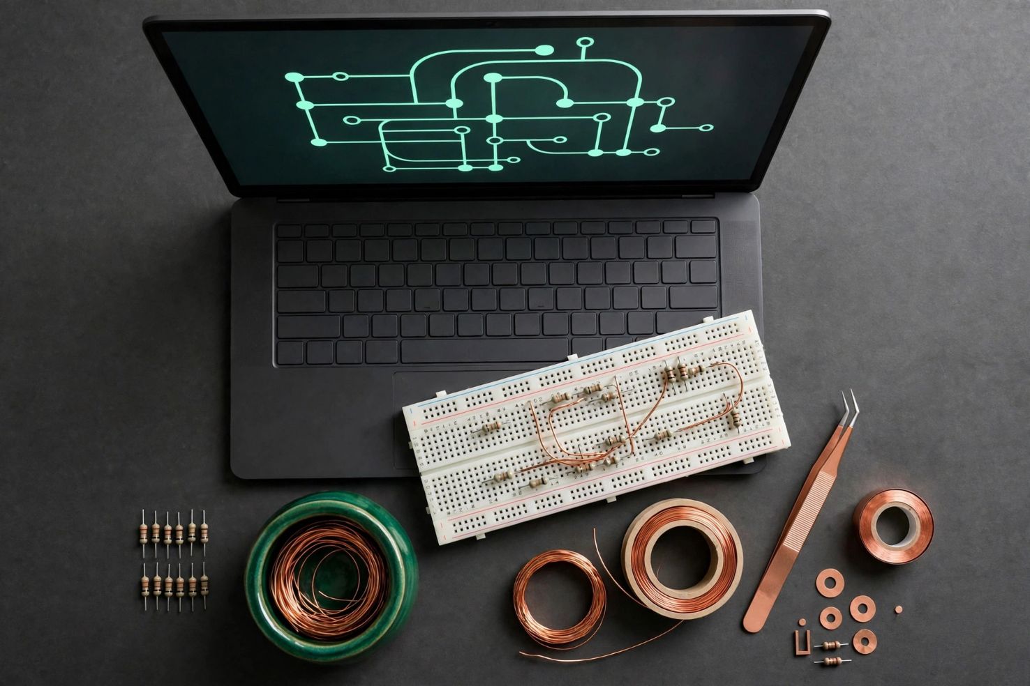
LTspice is a free SPICE simulator from Analog Devices with schematic capture and a waveform viewer [3][4]. The Analog Devices page describes it as fast and free with enhancements and models for analogue circuits [3]. For a student, the practical difference from a browser sketchpad is precision. LTspice lets you run transient, AC and DC analyses with device models and then inspect the waveform point by point instead of judging a moving animation.[3][4][13]
LTspice is offered as a free download for Windows and macOS from Analog Devices [3]. Keep the platform claim at that level. Older guides disagree about exact macOS version numbers, so this article makes no version-number claim for macOS and no claim about a native Linux build. A student on Linux should check the current Analog Devices download page before assuming support rather than relying on an old forum post about unofficial workarounds.[3][4][13]
The waveform viewer is where LTspice earns its place in a study routine. You can measure a peak, check a settling time and compare two runs after changing one value. That discipline turns a vague feeling that a circuit works into a number you can write in a lab report. Analog Devices also publishes getting-started material and demo circuits for LTspice, so a beginner does not have to learn the interface alone [13].[3][4][13]
The engine underneath: ngspice
ngspice is the open-source SPICE simulator that sits underneath several friendlier tools. It is the successor to Berkeley spice3f5 and it solves circuit equations from a netlist, which is a text description of components and connections [9]. KiCad uses ngspice as its simulation engine, which means a student who learns ngspice concepts once can recognise them again inside KiCad later.[9]
ngspice has no built-in schematic capture with automatic netlist generation [9]. That sounds like a drawback and in one sense it is. A beginner who wants to draw a circuit and press run will find KiCad or Qucs-S more welcoming. The value of ngspice on its own is transparency. A netlist shows exactly what the simulator was asked to solve, which makes it easier to spot a wrong connection or a missing model.[9]

One front end for SPICE: Qucs-S
Qucs-S is free and open-source software that provides a graphical circuit design and simulation environment using external SPICE backends including Ngspice, Xyce and SpiceOpus [10][11]. For a student, that sentence matters because it separates two jobs. Qucs-S handles drawing and results while a SPICE engine handles the maths. If one engine lacks a feature, another backend may cover it without forcing a change of drawing tool.[10][11]
Qucs-S is the active SPICE-integrated fork to choose for new work rather than the older original Qucs, which is tied to older libraries that no longer install cleanly on current systems. That distinction saves a beginner from a frustrating first install. The lesson generalises well. In open-source electronics, the actively maintained fork often matters more than the famous name. A quick check of maintenance status belongs in any tool choice.[10][11]
Qucs-S suits a student who has outgrown a browser simulator and wants a graphical SPICE workflow without committing to a full PCB suite yet. It is a middle step with real value. It teaches schematic discipline and model use while keeping the focus on circuit behaviour rather than board layout, copper pours and manufacturing files.[10][11]
From schematic to a board you can hold: KiCad
KiCad is a free open-source electronic design automation suite for schematic capture and printed circuit board layout under GPL-3.0 [1]. It runs on Windows, macOS and Linux [2]. For a student, KiCad is the tool where a course project stops being a diagram and starts becoming a physical object. You draw a schematic, you assign footprints, you lay out a board and you generate the files a manufacturer would need.[1][2]
KiCad integrates ngspice in graphical form through the Schematic Editor, with AC Sweep, DC Transfer, Operating Point and Transient modes [1]. That integration means a student can simulate inside the same project that will later become a board. The workflow stays coherent though. That coherence is why KiCad belongs at the end of the sequence rather than at the start.[1][2]
KiCad does not currently bundle third-party SPICE libraries, so students normally obtain device models from manufacturers [1]. That is a practical detail worth knowing before a first simulation. A missing model is not a broken tool. It is a normal step in professional work. Learning to find and check a manufacturer model is itself a useful skill. KiCad documentation includes a getting-started guide that walks through the schematic-to-board workflow for beginners [2].[1][2]
A sensible order for a semester
A student can start with a visual browser simulator for intuition, move to a full SPICE simulator for precision and model-based checks, then use KiCad to turn a tested schematic into a PCB layout. That order matches how understanding grows. First you see what a circuit does. Then you measure what it does. Then you build it in a form that other people can reproduce.[1]
Week one suits Falstad or Tinkercad Circuits depending on whether the course starts with analogue basics or Arduino code. Week two or three suits LTspice or Qucs-S for a circuit that needs a number rather than an animation. A later project suits KiCad, when the goal is a board rather than a single answer. No step needs to be abandoned. A browser simulator remains useful for a quick sanity check even after a student can run SPICE.[1]
The order also protects a budget. Every tool in this article is free for the core work described here, so a student can follow the whole sequence without a purchase decision in the middle of a term. That matters because a paid tool that expires mid-project can strand a student at the worst moment. Free and open tools remove that risk while teaching skills that transfer to paid tools later if an employer uses them.[1]
What simulation cannot prove
A simulation result is a model result rather than proof of a safe real circuit. Results depend on topology, device models, parasitics, source waveforms, initial conditions, tolerances, temperature and solver settings [14]. Change any of those inputs and the output can change. A passing simulation therefore answers a narrower question than students sometimes assume. It shows that a model of a circuit behaves in a certain way under stated conditions.[14]
A schematic simulation that omits layout parasitics does not automatically account for trace inductance, thermal performance, EMI, manufacturing variation or every protection mechanism in a real component [14]. A power stage that looks fine on screen can overheat on a board. A fast signal that looks clean in simulation can ring once it travels along a real trace. Those effects are not reasons to distrust simulation. They are reasons to treat simulation as one check among several.[14]
A first project that teaches the whole chain
A good first project uses every step without needing expensive parts. Start in Falstad with a simple LED circuit driven through a resistor and watch how current changes with resistor value. Move the same idea to Tinkercad Circuits if the course uses Arduino. Add code that blinks the LED at a set rate. The goal at this stage is intuition and wiring sense rather than precision.[1]
Next, rebuild the analogue part in LTspice or Qucs-S and run a transient analysis. Measure the LED current and the resistor voltage drop. Compare the numbers with a hand calculation using Ohm's law. If they disagree, check the model and the resistor value before assuming the simulator is wrong. That comparison teaches more than either method alone because it forces a student to reconcile two independent answers.[1]
Finally, draw the circuit in KiCad and lay out a small board, even if the board is never manufactured. The layout step forces decisions about component placement and trace routing that a schematic hides. A student who completes that chain has practised intuition, measurement, modelling and manufacturing thinking in one project, using only free tools.[1]
Free learning paths that cost nothing else
Students can learn for free from the official KiCad Getting Started guide, the official ngspice beginner tutorial and Analog Devices LTspice tutorials plus demo circuits and EngineerZone support [2][9][13]. Those official sources matter because they match the current software version. A random video from five years ago can show menus that no longer exist, while official guides are updated with the tool.[2][9][13]
A sensible study habit is to follow one official guide end to end before collecting tips from many sources. Finish the KiCad getting-started project. Work through the ngspice beginner tutorial. Run one Analog Devices LTspice demo and change one value at a time. Depth in one guide beats a folder of half-finished tutorials. A completed example gives a student a working reference for the next project.[2][9][13]
Free learning also includes the habit of reading datasheets. A simulator model is only as good as its parameters. Those parameters come from manufacturer documents. Students who read a datasheet for a transistor or an op-amp before simulating it will make fewer modelling mistakes and will recognise a missing model much earlier. That reading skill transfers to every electronics job, whatever tool an employer provides.[2][9][13]
What to check before you trust a result
Before trusting a simulation, check four things in order. First, check the schematic itself for a wrong connection or a missing ground, because the most common simulation failure is a drawing error rather than a maths error. Second, check the model source and whether it came from the manufacturer or from a generic library with unknown limits. Third, check the analysis settings, including start time, step size and temperature, because a transient result can hide a problem that a different time window would reveal.[1]
Fourth, check the result against a second method. A hand calculation, a second simulator or a bench measurement can each catch a different kind of error. If two methods agree, confidence rises. If they disagree, the disagreement points to the next question rather than ending the investigation. That checking routine is the real skill simulation teaches. It stays useful long after any particular tool version changes.[1]
Questions, answered.
Is KiCad really free for students?
Yes. KiCad is a free open-source suite under GPL-3.0 with no paid unlock needed for schematic capture, simulation or PCB layout [1].[1]
Do I need to install anything to start simulating?
No, not at first. Falstad and Tinkercad Circuits run in a browser, so a student can start with no installation step [5][7].[5][7]
Can simulation replace lab work completely?
No. Simulation is a model result and it cannot by itself prove power, thermal, layout or EMI behaviour in a real circuit [14]. Bench testing still matters.[14]
Which tool should an electronics student learn first?
Start with a visual browser simulator for intuition, move to LTspice or Qucs-S for model-based checks and finish with KiCad for PCB layout.[1]
Is Tinkercad Circuits free?
Yes, with a free Autodesk account for the normal classroom workflow including saving work [7][8].[7][8]
Does LTspice work on every operating system?
This article claims Windows and macOS support from Analog Devices [3]. It makes no claim about a native Linux build, so Linux users should check the current download page first.[3]
Read the sources.
- SPICE Simulation | KiCadKiCad · Accessed 2026-11-10
- Getting Started in KiCad | 9.0KiCad documentation · Accessed 2026-11-10
- LTspice | Analog DevicesAnalog Devices · Accessed 2026-11-10
- What is LTspice?DigiKey TechForum · Accessed 2026-11-10
- 11.13: Circuit SimulatorLibreTexts Engineering · Accessed 2026-11-10
- Electrical circuit simulation: falstad.com/circuitTU Berlin DiBeLe project · Accessed 2026-11-10
- Arduino Simulators for Hobbyists, Makers, and Classroom EnvironmentsDigiKey · Accessed 2026-11-10
- Exercise: Introduction to Tinkercad CircuitsCarnegie Mellon University · Accessed 2026-11-10
- ngspice tutorial for beginnersngspice project · Accessed 2026-11-10
- Qucs-S - graphical interface for SPICE circuit simulationLinuxLinks · Accessed 2026-11-10
- QUCS: Your Open-Source Electronics LabElectronics For You · Accessed 2026-11-10
- Falstad's Circuit SimulatorUniversity of Illinois ECE 110 · Accessed 2026-11-10
- Getting Started with LTspiceAnalog Devices EngineerZone · Accessed 2026-11-10
- LTspice Circuit Simulation Guide: Analyses, Models, and TroubleshootingUMA Technology · Accessed 2026-11-10
- 11 Free Online Circuit Simulators- 2026(Tried and Tested)eTechnophiles · Accessed 2026-11-10
- 10 Best Free Circuit Simulators You Can Use onlineElectronics Curiosities · Accessed 2026-11-10
Contributor articles and source links do not guarantee error-free reporting. See our editorial policy.