Navigate this guide · 1,592 words
The essential signal
- For ordinary baseband acquisition, unwanted energy above half the sample rate can fold into the useful band.
- An analog anti-alias filter acts before sampling; a later digital filter cannot reliably undo overlapping signals.
- Design margin must include filter roll-off, interference and ADC input behavior, not only the wanted signal frequency.
Sampling records moments, not everything between them
An analog-to-digital converter measures a signal at separate instants, producing a sequence of numbers rather than a continuous record. A smooth-looking digital plot does not prove that this sequence uniquely represents the original analog input. Analog Devices explains aliasing as the appearance of higher-frequency components inside the frequency band of interest when the sampling relationship is unsuitable. This can make a measurement look believable while representing the wrong frequency content. For an EEE measurement project, that is an important distinction: the converter can produce stable numbers and the software can draw an attractive curve while the acquisition system is still misleading.[1][2]
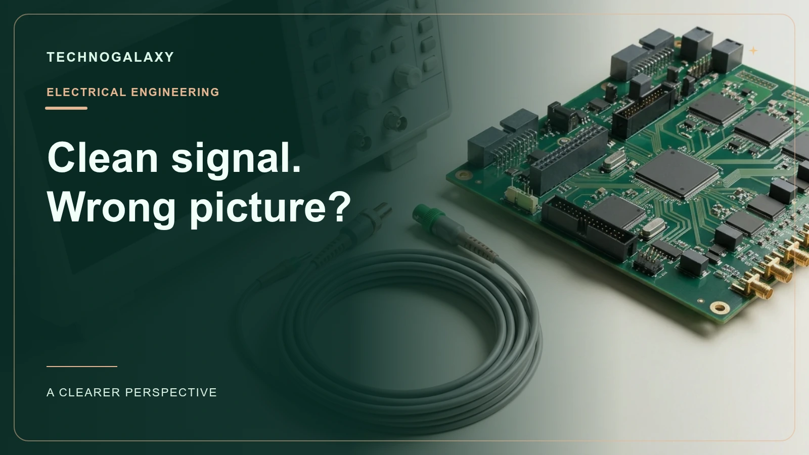
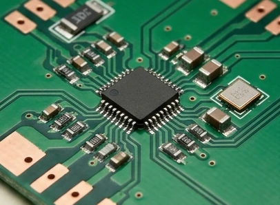
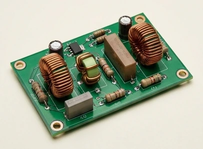
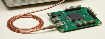
Before comparing bit counts, trace the signal all the way from its source to the converter. Ask which frequencies reach the analog input, how strongly they appear and which sampling rate is actually used. A sensor's intended signal is only part of the input; interference and broadband noise also matter. The illustrations in this article show laboratory objects, not working circuits or verified test setups. The aim is to explain how to reason about a measurement chain. Component selection, protection and implementation still require the converter's documentation and an appropriate engineering review.[1][2]
The Nyquist boundary is not a comfortable design margin
In ordinary baseband acquisition, the Nyquist frequency is half the sampling rate. The input must be appropriately band-limited if the sampled data is to represent the desired band without unwanted folding. Analog Devices uses twice the highest input frequency as the idealized boundary and notes that practical sampling is usually higher to provide margin. Treat that relationship as the beginning of the design, not the entire specification. Real filters do not abruptly remove all energy at one frequency, and a signal exactly at the boundary leaves problematic phase-sensitive cases.[1][2]
Suppose, as a hypothetical example, that the signal you want to measure contains useful information up to 1 kilohertz. Choosing a 2-kilosample-per-second converter solely because the arithmetic says two times one ignores the filter's transition region and other input energy. A more useful review asks how the unwanted frequencies will be attenuated before sampling and whether the converter can settle correctly at the selected rate. This example is not a prescribed sampling frequency for any product. It is a reminder that the relevant bandwidth belongs to the complete analog signal arriving at the ADC, not only the feature the engineer hopes to observe.[1][2]
How a higher frequency becomes a lower one
Sampling creates repeated versions of the signal's spectrum, spaced according to the sampling rate. When those copies overlap the band of interest, different analog signals can become indistinguishable in the sampled representation. As a simple hypothetical example, sampling a 900-hertz sinusoid at 1,000 samples per second produces an apparent 100-hertz component. The sample sequence does not carry a convenient flag announcing that the low-frequency appearance came from a higher-frequency input. That ambiguity is the practical problem behind aliasing, not merely an untidy plot or a numerical rounding error.[1][2]
That explanation assumes evenly spaced samples and the usual interpretation of a sinusoidal signal. It is not a claim that every waveform becomes one particular alias or that a digital graph alone identifies the original source. A suggested diagnostic exercise is to vary the acquisition rate in a controlled test and observe whether suspicious spectral features move as the alias relationship predicts. Use an appropriate signal source and safe bench setup. The more important preventative step remains controlling the input spectrum. Discovering an alias after data collection may reveal the problem, but it does not restore information that was never uniquely captured.[1][2]
The filter belongs before the ambiguity
An analog anti-alias filter reduces unwanted frequencies before the converter takes its samples. Analog Devices distinguishes this role from digital filtering after conversion. If an unwanted signal has already folded onto a desired signal at the same apparent frequency, a later digital filter cannot reliably separate them using frequency alone. It sees the combined sampled content, not a complete record of how the original analog components arrived. This is why a software-only smoothing option is not a universal repair for an inadequately controlled analog input.[1][2]
Digital filtering still has an important role; it simply cannot undo every problem created during sampling. They can shape the retained band, reduce certain noise contributions and prepare oversampled data for a lower output rate. The mistake is assigning them a task that requires information sampling has already made ambiguous. A suggested architecture review draws separate boxes for analog filtering, ADC sampling and digital processing, then states what each box is intended to remove. If the design relies on digital filtering to remove every analog interferer, check that assumption carefully. The relevant answer depends on the ADC topology, its internal sampling and the documented filtering chain.[1][2]
Real filters have a transition region
A perfect brick-wall filter would separate wanted and unwanted frequencies at one sharp boundary. Real filters instead have finite attenuation, a transition band and effects on phase or group delay. Analog Devices discusses passband flatness, stopband rejection and transition steepness as design considerations. These properties compete with one another and with implementation complexity. A steep filter may address close-in interference while introducing other constraints. A gentle filter may preserve a desired waveform well but require greater separation between the useful band and troublesome input frequencies.[1][2]
A useful filter specification needs more than a single cutoff number. Record the acceptable in-band amplitude error, required attenuation at important interferers and any timing requirements. Also document which input disturbances are known and which are uncertain. Two filters with the same nominal cutoff can behave differently where the application needs rejection. Avoid treating a generic component calculator as evidence that the complete measurement chain meets an error budget. Simulation can support design, but tolerances, actual loading and measurements still need consideration. The useful question is how the filter behaves across the frequencies and conditions that matter.[1][2]
The ADC input changes the filter problem
As the precision-ADC article explains, a filter also has to work with the converter's nonideal input circuitry. A simple resistor-capacitor network may attenuate noise, but its bandwidth and settling behavior affect the converter's ability to acquire an accurate value. The source discusses an example where reducing bandwidth creates substantial amplitude attenuation and acquisition difficulties. That is a case-specific result, not a universal percentage to apply to every circuit. The broader lesson is that an ADC input is not always an ideal observer that leaves the preceding filter unchanged.[1][2]
Check the input model, acquisition time and recommended driver before settling on a filter. Suggested bench checks examine settling after a change in input, behavior near full scale and performance across intended operating conditions. If multiple channels share a converter, the measurement sequence deserves particular attention because changes between channels can create additional settling requirements. This is not an instruction to connect arbitrary voltages to a development board. Stay within documented ratings and use appropriate protection. Good signal-chain reasoning accounts for the interaction among source impedance, filtering, driver behavior and the converter itself.[1][2]
Oversampling helps, but does not abolish constraints
Sampling faster internally can give an analog filter more transition room and make useful digital processing possible. Analog Devices describes oversampling and subsequent band-limiting as ways to improve in-band performance under appropriate noise assumptions. It also notes that theoretical improvements based on ideal quantization noise do not automatically represent the complete real signal chain. Other noise sources and converter limitations remain. A faster ADC therefore changes the design trade-offs; it does not guarantee that every measurement becomes more accurate or that analog filtering can always be removed.[1][2]
Lowering the output sample rate creates a new boundary that also needs filtering consideration. Before decimation, a digital filter must adequately limit the retained spectrum relative to the lower rate. Otherwise, the processing stage can create its own aliasing problem. A suggested data-flow review records the rate at every stage rather than using one sample-rate label for the whole system. Distinguish the ADC's internal operation, filtered output rate and the rate ultimately stored or plotted. The final stream may look slow and clean even though the acquisition process is more complex. Documenting those stages makes the design easier to test and explain.[1][2]
Keep resolution and bandwidth separate
Bit count describes the converter's numerical scale; it does not prove the analog signal was sampled without ambiguity. Increasing the number of bits cannot distinguish two signals that produce the same sampled sequence. A clear specification worksheet therefore gives resolution, sampling rate, intended bandwidth and filtering separate entries. The Analog Devices discussions treat filtering and signal-chain behavior as essential alongside converter characteristics. Retain those distinctions when reading a development-board advertisement: a high-resolution converter can still produce misleading measurements if the input spectrum and acquisition process are unsuitable.[1]
A practical measurement checklist
Begin by writing down the frequency band you need and the disturbances that could reach the input. Choose sampling and filtering together, then check passband accuracy, rejection, input settling and the effect of later rate changes. Analog Devices also describes intentional undersampling in selected applications, so aliasing should not be treated as universally accidental. However, deliberate bandpass sampling requires control of the input bands and a different design analysis. It is not a justification for ignoring filtering in an ordinary baseband sensor project or assuming that every apparent low-frequency component is genuine.[1][2]
For a student experiment, state the expected result before each test: the frequency you expect, the amplitude change and the result that would expose a mistaken assumption. Compare the observation with the planned signal path rather than judging only whether the plot looks smooth. Retain the actual sample-rate settings and filter configuration with the dataset. A reliable ADC project is an evidence chain from analog input to stored samples. The goal is not the prettiest waveform, but a measurement whose bandwidth, limitations and processing history are sufficiently clear for another person to reproduce and evaluate.[1][2]
Questions, answered.
Can a digital filter remove all aliasing after conversion?
No. Once an unwanted component overlaps wanted content in the sampled band, frequency-based post-processing cannot reliably recover their original separation.[1]
Is twice the desired signal frequency always enough?
It is an idealized boundary for suitably band-limited baseband signals, not a practical filter and settling margin.[1]
Read the sources.
- Filter basics: anti-aliasingAnalog Devices · Accessed 2026-10-14
- Practical filter design challenges for precision ADCsAnalog Devices · Accessed 2026-10-14
AI assistance and source checks reduce risk; they do not guarantee error-free reporting. See our editorial policy.